文章信息
- 袁燕岭, 李凯特, 董杰, 高俊福, 李世松, 赵伟
- YUAN Yanling, LI Kaite, DONG Jie, GAO Junfu, LI Shisong, ZHAO Wei
- 三芯电力电缆各芯线电流测量偏心误差的计算和补偿方法
- Calculation and compensation method for eccentric error of current measurement of each core wire of three-core power cable
- 中国测试, 2019, 45(1): 19-26
- CHINA MEASUREMENT & TEST, 2019, 45(1): 19-26
- http://dx.doi.org/10.11857/j.issn.1674-5124.2018050024
-
文章历史
- 收稿日期: 2018-05-09
- 收到修改稿日期: 2018-07-12
2. 清华大学电机工程与应用电子技术系 电力系统及发电设备控制和仿真国家重点实验室,北京 100084
2. State Key Laboratory of Control and Simulation of Power System and Generation Equipment, Department of Electrical Engineering, Tsinghua University, Beijing 100084, China
随着三芯电力电缆越来越多地应用于35 kV及以下三相电力系统的电缆输配电工程中[1],其运行的安全性日益受到重视[2]。为实现对三芯电力电缆运行状态的在线监测,一种较为可靠的方法是监测三芯电力电缆实际运行中各芯线的电流[3]。在电力系统运行中,对三芯电缆各芯线电流的监测意义重大。原则上,可通过实时监测,对三芯电力电缆的运行状态和其是否存在潜在的故障等进行评估,以确保经三芯电力电缆传输电力的安全可靠。
然而,对各相芯线共同使用同一屏蔽保护层的三芯电力电缆而言,传统的基于电磁感应原理、以电流互感器测量电流的方法无法被应用。这是因为,三芯电力电缆的A、B、C三相芯线一般两两相隔120°沿该电缆轴向圆周均匀分布,且三相芯线使用共同的屏蔽保护层,在三芯电力电缆正常、对称稳定的运行情况下,三相电流平衡,对外的等效电流为零,即穿过该电缆轴向横截面的总磁通量也为零。因此,不能在环绕电缆轴向的磁感应平面上产生变化的磁通量,因而就无法以电流互感器测量三芯电力电缆各芯线的电流。
目前已有的三芯电力电缆监测方法,多是基于间接方法来反映三芯电力电缆的运行特性,例如通过测量三芯电力电缆的温度等来监测三芯电力电缆的运行状态[4-7]。间接方法虽然也能反映三芯电力电缆是否存在发生故障的隐患甚至已发生故障,但测量往往存在延迟,且难以明确诊断故障的具体位置和类型,存在较大的局限性。
近年来,随着磁测量技术的发展和磁传感器制造工艺水平的不断提高,用磁传感器测量电流逐渐成为电力行业认可的一种方法[8-9]。本文作者之前通过在三芯电力电缆表面安装与各芯线准直且空间上互差120°的3个磁传感器(以下简称“磁传感器阵列”),线性地感知并获取到三芯电力电缆各芯线电流的大小[10]。但在实施该测量方法时,磁传感器阵列的中心必须要与三芯电力电缆的中心(以下简称“电缆中心”)重合,否则,就会产生相应的测量误差[11-12],也称偏心误差。对于实际的测量装置,由于受装置制作的工艺水准和装置安装时施工人员的操作水平等因素限制,磁传感器阵列中心与电缆中心之间难免存在毫米量级的偏心。而三芯电力电缆周围任意位置由某相电流产生的磁感应强度,与该相电缆芯线到该位置之间的距离成反比,即其对位置的变化比较敏感。故,对偏心误差必须加以考虑。
为了计算并补偿偏心误差,以更准确地测量三芯电力电缆各芯线的电流,本文提出一种磁传感器阵列“旋转法”,建立三芯电力电缆各芯线电流、磁传感器阵列中心实际位置以及所测量磁感应强度相互关联的解析模型,求解得到偏心误差,以及考虑偏心误差条件下三芯电力电缆各芯线电流的实际大小。
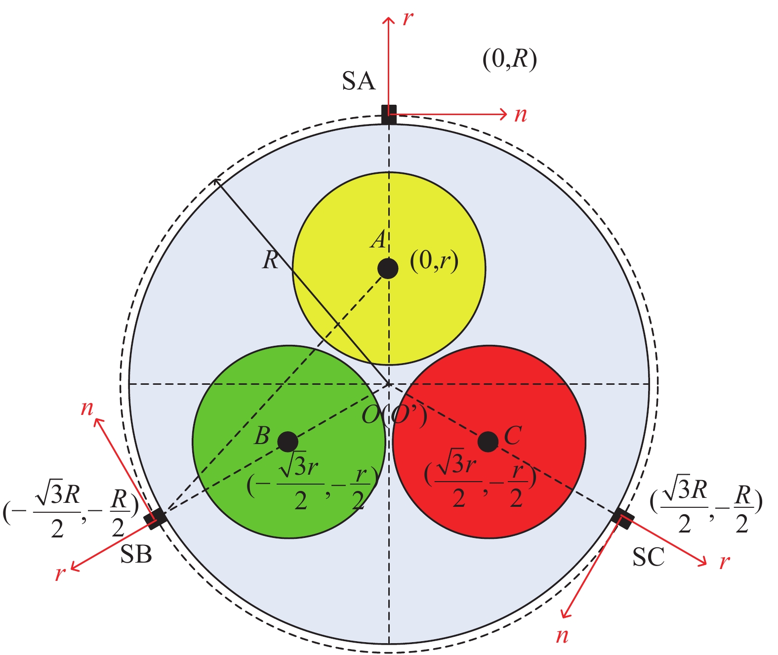
1 计算三芯电力电缆表面磁感应强度的解析模型 1.1 磁传感器阵列中心与电缆中心无偏心时三芯电力电缆表面磁感应强度的解析模型磁传感器阵列中心与电缆中心重合即不存在偏心时,三芯电力电缆的结构及各芯线电流的测量原理,如图1所示。电缆中心为O,A、B、C分别为三相芯线的中心,电缆中心O到三相芯线中心A、B、C的距离均为r;OA、OB、OC互成120°;SA、SB、SC为3个磁传感器的安装位置,其到磁传感器阵列中心O’(x,y)的距离均为R;3个磁传感器均测量所在位置磁感应强度沿电缆外表面轴向圆周的切向分量,即n方向的分量。不失一般性,可使y轴与OA重合,则A点的坐标为(0, r);电缆中心到B、C两芯线中心的矢量,即OB、OC与x轴的夹角就分别为210°、330°;B点的坐标为(–
|
| 图 1 磁传感器阵列中心与电缆中心无偏心时三芯电力电缆结构及各芯线电流的测量原理 |
首先,给出磁传感器阵列中心与电缆中心重合即无偏心时,使用磁传感器测量三芯电力电缆各芯线电流的解析模型。本文规定电流方向向内为正,根据安培环路定理,由A相电流IA在SA处产生的磁感应强度为
| ${B_{{\rm{SA - A}}}} = \frac{{{\mu _0}{I_{\rm{A}}}}}{{2\pi (R - r)}}$ | (1) |
其中μ0为真空磁导率。
式(1)中的磁感应强度即指向n方向。类似地,由B相电流IB在SA处产生的磁感应强度为
| ${B_{{\rm{SA - B}}}} = \frac{{{\mu _0}{I_{\rm{B}}}}}{{2\pi \sqrt {{{\left( {R + \displaystyle\frac{r}{2}} \right)}^2} + {{\left( {\displaystyle\frac{{\sqrt 3 r}}{2}} \right)}^2}} }}$ | (2) |
式(2)中磁感应强度BSA-B的方向为
| $\left( {\frac{{R + \displaystyle\frac{r}{2}}}{{\sqrt {{{\left( {R + \displaystyle\frac{r}{2}} \right)}^2} + {{\left( {\displaystyle\frac{{\sqrt 3 r}}{2}} \right)}^2}} }},\frac{{ - \displaystyle\frac{{\sqrt 3 r}}{2}}}{{\sqrt {{{\left( {R + \displaystyle\frac{r}{2}} \right)}^2} + {{\left( {\displaystyle\frac{{\sqrt 3 r}}{2}} \right)}^2}} }}} \right)$ | (3) |
故,BSA-B中沿n方向的分量为
| ${B_{{\rm S}{\rm{A - B}}n}} = \frac{{{\mu _0}{I_{\rm{B}}}\left( {R + \displaystyle\frac{r}{2}} \right)}}{{2\pi \left[ {{{\left( {R + \displaystyle\frac{r}{2}} \right)}^2}{\rm{ + }}{{\left( {\displaystyle\frac{{\sqrt 3 r}}{2}} \right)}^2}} \right]}}$ | (4) |
同理,由C相电流IC在SA处产生的磁感应强度为
| ${B_{{\rm{SA - C}}}} = \frac{{{\mu _0}{I_{\rm{C}}}}}{{2\pi \sqrt {{{\left( {R + \displaystyle\frac{r}{2}} \right)}^2} + {{\left( { - \displaystyle\frac{{\sqrt 3 r}}{2}} \right)}^2}} }}$ | (5) |
式(5)所示磁感应强度BSA-C的方向为
| $\left( {\frac{{R + \displaystyle\frac{r}{2}}}{{\sqrt {{{\left( {R + \displaystyle\frac{r}{2}} \right)}^2} + {{\left( { - \displaystyle\frac{{\sqrt 3 r}}{2}} \right)}^2}} }},\frac{{\displaystyle\frac{{\sqrt 3 r}}{2}}}{{\sqrt {{{\left( {R + \displaystyle\frac{r}{2}} \right)}^2} + {{\left( { - \displaystyle\frac{{\sqrt 3 r}}{2}} \right)}^2}} }}} \right)$ | (6) |
故,BSA-C中沿n方向的分量为
| ${B_{{\rm S}{\rm{A - C}}n}} = \frac{{{\mu _0}{I_{\rm{C}}}\left( {R + \displaystyle\frac{r}{2}} \right)}}{{2\pi \left[ {{{\left( {R + \displaystyle\frac{r}{2}} \right)}^2} + {{\left( { - \displaystyle\frac{{\sqrt 3 r}}{2}} \right)}^2}} \right]}}$ | (7) |
联立式(1)、式(4)和式(7),可得到在SA处由三相芯线电流共同产生的磁感应强度沿n方向的分量为
| ${B_{{\rm{SA - }}n}} = \displaystyle\frac{{{\mu _0}}}{{2\pi }}\left[ {\displaystyle\frac{{{I_{\rm{A}}}}}{{R - r}}{\rm{ + }}\displaystyle\frac{{\left( {R + \displaystyle\frac{r}{2}} \right)({I_{\rm{B}}}{\rm{ + }}{I_{\rm{C}}})}}{{{{\left( {R + \displaystyle\frac{r}{2}} \right)}^2}{\rm{ + }}{{\left( {\displaystyle\frac{{\sqrt 3 r}}{2}} \right)}^2}}}} \right]$ | (8) |
考虑到三芯电力电缆结构上的对称性,在求解SB、SC处的磁感应强度时,可将x和y坐标轴进行旋转。例如,在求解SB处的磁感应强度时,就可将y轴旋转至与OB相重合。如此,OC、OA与x轴的夹角分别为210°、330°。因此,在进行具体计算上,基于式(1)、式(4)、式(7)和式(8),只要在磁传感器SA处的磁感应强度沿n方向分量的表达式中,将IA换成IB,IB换成IC,IC换成IA,即将三相芯线电流进行如此的依次轮换即可。由此方法,即可得到SB处的磁感应强度沿n方向的分量为
| ${B_{{\rm{SB - }}n}} = \frac{{{\mu _0}}}{{2\pi }}\left[ {\frac{{{I_{\rm{B}}}}}{{R - r}}{\rm{ + }}\frac{{\left( {R + \displaystyle\frac{r}{2}} \right)({I_{\rm{C}}}{\rm{ + }}{I_{\rm{A}}})}}{{{{\left( {R + \displaystyle\frac{r}{2}} \right)}^2}{\rm{ + }}{{\left( {\displaystyle\frac{{\sqrt 3 r}}{2}} \right)}^2}}}} \right]$ | (9) |
同理,也可得到SC处的磁感应强度沿n方向的分量为
| ${B_{{\rm{SC - }}n}} = \frac{{{\mu _0}}}{{2\pi }}\left[ {\displaystyle\frac{{{I_{\rm{C}}}}}{{R - r}}{\rm{ + }}\frac{{\left( {R + \displaystyle\frac{r}{2}} \right)({I_{\rm{A}}}{\rm{ + }}{I_{\rm{B}}})}}{{{{\left( {R + \displaystyle\frac{r}{2}} \right)}^2}{\rm{ + }}{{\left( {\displaystyle\frac{{\sqrt 3 r}}{2}} \right)}^2}}}} \right]$ | (10) |
由于BSA-n、BSB-n和BSC-n均为磁传感器的测量值,联立由式(8)~式(10)组成的方程组,便可推导出IA、IB和IC解析表达式,具体分别为
| $ \begin{split} {I_{\rm{A}}} = &\displaystyle\frac{{2\pi (R - r)({R^2} + rR + {r^2})}}{{9{\mu _0}r{R^2}(R + r)}} \times \left[ {(4{R^2} + rR + {r^2})}{B_{{\rm{SA - }}n}} +\right. \\ & \left.{ ( - 2{R^2} + rR + {r^2})({B_{{\rm{SB - }}n}} + {B_{{\rm{SC - }}n}})} \right] \quad\quad\quad\quad\quad\quad \end{split} $ | (11) |
| $ \begin{split} {I_{\rm B}} = &\displaystyle\frac{{2\pi (R - r)({R^2} + rR + {r^2})}}{{9{\mu _0}r{R^2}(R + r)}} \times \left[ {(4{R^2} + rR + {r^2})}{B_{{\rm{SB - }}n}} +\right. \\ &\left.{ ( - 2{R^2} + rR + {r^2})({B_{{\rm{SC - }}n}} + {B_{{\rm{SA - }}n}})} \right]\quad\quad\quad\quad\quad\quad \end{split} $ | (12) |
| $\begin{split} {I_{\rm{C}}} = &\displaystyle\frac{{2\pi (R - r)({R^2} + rR + {r^2})}}{{9{\mu _0}r{R^2}(R + r)}} \times \left[ {(4{R^2} + rR + {r^2})}{B_{{\rm{SC - }}n}} +\right.\\ &\left.{ ( - 2{R^2} + rR + {r^2})({B_{{\rm{SA - }}n}} + {B_{{\rm{SB - }}n}})} \right] \quad\quad\quad\quad\quad\quad \end{split} $ | (13) |
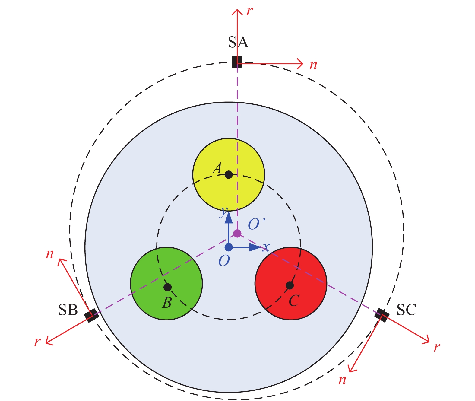
图2给出了磁传感器阵列中心与电缆中心之间存在偏心的原理示意图。据此,SA、SB、SC 3个磁传感器安装位置的坐标分别为(x,y+R)、(x–
|
| 图 2 磁传感器阵列中心与电缆中心存在偏心时各芯线电流的测量原理(初始测量位置,0°) |
根据图2,由A相电流IA在SA处产生的磁感应强度为
| ${B_{{\rm{SA - A}}}} = \frac{{{\mu _0}{I_{\rm{A}}}}}{{2\pi \sqrt {{{(R{\rm{ + }}y - r)}^2} + {x^2}} }}$ | (14) |
式(14)所示磁感应强度BSA-A的方向为
| $\left( {\frac{{R{\rm{ + }}y - r}}{{\sqrt {{{(R{\rm{ + }}y - r)}^2} + {x^2}} }},\frac{{ - x}}{{\sqrt {{{(R{\rm{ + }}y - r)}^2} + {x^2}} }}} \right)$ | (15) |
故,BSA-A中沿n方向的分量为
| ${B_{{\rm{SA - A}}n}} = \frac{{{\mu _0}{I_{\rm{A}}}(R{\rm{ + }}y - r)}}{{2\pi [{{(R{\rm{ + }}y - r)}^2} + {x^2}]}}$ | (16) |
类似地,由B相电流IB在SA处产生的磁感应强度为
| ${B_{{\rm{SA - B}}}} = \frac{{{\mu _0}{I_{\rm{B}}}}}{{2\pi \sqrt {{{\left( {R{\rm{ + }}y + \displaystyle\frac{r}{2}} \right)}^2} + {{\left( {x + \displaystyle\frac{{\sqrt 3 r}}{2}} \right)}^2}} }}$ | (17) |
式(17)所示磁感应强度BSA-B的方向为
| $ \left( \begin{aligned} \frac{R+ y + \displaystyle\frac{r}{2}} {\sqrt {{\left( R+ y + \displaystyle\frac{r}{2} \right)}^2 + {\left( {x + \displaystyle\frac{\sqrt 3 r}{2}} \right)}^2}}, \\ \frac{ - \left(x + \displaystyle\frac{\sqrt 3 r}{2}\right)}{\sqrt {{\left( {R + y + \displaystyle\frac{r}{2}} \right)}^2 + \left( {x + \displaystyle\frac{\sqrt 3 r}{2}} \right)^2} } \end{aligned}\right) $ | (18) |
故,BSA-B中沿n方向的分量为
| ${B_{{\rm{SA - B}}n}} = \frac{{{\mu _0}{I_{\rm{B}}}\left( {R{\rm{ + }}y + \displaystyle\frac{r}{2}} \right)}}{{2\pi \left[ {{{\left( {R{\rm{ + }}y + \displaystyle\frac{r}{2}} \right)}^2} + {{\left( {x + \displaystyle\frac{{\sqrt 3 r}}{2}} \right)}^2}} \right]}}$ | (19) |
同理,由C相电流IC在SA处产生的磁感应强度为
| ${B_{{\rm{SA - C}}}} = \frac{{{\mu _0}{I_{\rm{C}}}}}{{2\pi \sqrt {{{\left( {R{\rm{ + }}y + \displaystyle\frac{r}{2}} \right)}^2} + {{\left( {x - \displaystyle\frac{{\sqrt 3 r}}{2}} \right)}^2}} }}$ | (20) |
式(20)所示的磁感应强度BSA-C的方向为
| $ \left( \begin{aligned} \frac{{R + y + \displaystyle\frac{r}{2}}}{{\sqrt {{{\left( {R + y + \displaystyle\frac{r}{2}} \right)}^2} + {{\left( {x - \displaystyle\frac{{\sqrt 3 r}}{2}} \right)}^2}} }},\\ \frac{{ - (x - \displaystyle\frac{{\sqrt 3 r}}{2})}}{{\sqrt {{{\left( {R + y + \displaystyle\frac{r}{2}} \right)}^2} + {{\left( {x - \displaystyle\frac{{\sqrt 3 r}}{2}} \right)}^2}} }} \end{aligned}\right)$ | (21) |
故,BSA-C中沿n方向的分量为
| ${B_{{\rm{SA - C}}n}} = \frac{{{\mu _0}{I_{\rm{C}}}\left( {R{\rm{ + }}y + \displaystyle\frac{r}{2}} \right)}}{{2\pi \left[ {{{\left( {R{\rm{ + }}y + \displaystyle\frac{r}{2}} \right)}^2} + {{\left( {x - \displaystyle\frac{{\sqrt 3 r}}{2}} \right)}^2}} \right]}}$ | (22) |
联立式(16)、式(19)和式(22),可得到存在偏心条件下,在SA处由A、B、C三相芯线电流共同产生的磁感应强度沿n方向的分量为
| $\begin{array}{l} {B_{{\rm{SA - }}n}} = \\ \displaystyle\frac{{{\mu _0}}}{{2\pi }}\left[ \begin{array}{c} \displaystyle\frac{{(R + y - r)}}{{{{(R + y - r)}^2} + {x^2}}},\\ \displaystyle\frac{{\left( {R + y + \displaystyle\frac{r}{2}} \right)}}{{{{\left( {R + y + \displaystyle\frac{r}{2}} \right)}^2} + {{\left( {x + \displaystyle\frac{{\sqrt 3 r}}{2}} \right)}^2}}},\\ \displaystyle\frac{{\left( {R + y + \displaystyle\frac{r}{2}} \right)}}{{{{\left( {R + y + \displaystyle\frac{r}{2}} \right)}^2} + {{\left( {x - \displaystyle\frac{{\sqrt 3 r}}{2}} \right)}^2}}}\\ \end{array} \right]\left[ \begin{array}{l} {I_{\rm{A}}}\\ {I_{\rm{B}}}\\ {I_{\rm{C}}} \end{array} \right] \end{array}$ | (23) |
类似地,可得到由A、B、C三相芯线电流在SB处产生的磁感应强度沿n方向的分量分别为
| ${B_{{\rm{SB - A}}n}} = \frac{{{\mu _0}{I_{\rm{A}}}\left[ { - \displaystyle\frac{1}{2}\left( {y - \displaystyle\frac{R}{2} - r} \right) - \displaystyle\frac{{\sqrt 3 }}{2}\left( {x - \displaystyle\frac{{\sqrt 3 R}}{2}} \right)} \right]}}{{2\pi \left[ {{{\left( {y - \displaystyle\frac{R}{2} - r} \right)}^2} + {{\left( {x - \displaystyle\frac{{\sqrt 3 R}}{2}} \right)}^2}} \right]}}$ | (24) |
| ${B_{{\rm{SB - B}}n}} = \frac{{{\mu _0}{I_{\rm{B}}}\left[ { - \displaystyle\frac{1}{2}\left( {y - \displaystyle\frac{R}{2}{\rm{ + }}\displaystyle\frac{r}{2}} \right) - \frac{{\sqrt 3 }}{2}\left( {x - \displaystyle\frac{{\sqrt 3 R}}{2} + \displaystyle\frac{{\sqrt 3 r}}{2}} \right)} \right]}}{{2\pi \left[ {{{\left( {y - \displaystyle\frac{R}{2}{\rm{ + }}\displaystyle\frac{r}{2}} \right)}^2} + {{\left( {x - \displaystyle\frac{{\sqrt 3 R}}{2} + \displaystyle\frac{{\sqrt 3 r}}{2}} \right)}^2}} \right]}}$ | (25) |
| ${B_{{\rm{SB - C}}n}} = \frac{{{\mu _0}{I_{\rm{C}}}\left[ { - \displaystyle\frac{1}{2}\left( {y - \displaystyle\frac{R}{2}{\rm{ + }}\displaystyle\frac{r}{2}} \right) - \displaystyle\frac{{\sqrt 3 }}{2}\left( {x - \frac{{\sqrt 3 R}}{2} - \displaystyle\frac{{\sqrt 3 r}}{2}} \right)} \right]}}{{2\pi \left[ {{{\left( {y - \displaystyle\frac{R}{2}{\rm{ + }}\displaystyle\frac{r}{2}} \right)}^2} + {{\left( {x - \displaystyle\frac{{\sqrt 3 R}}{2} - \displaystyle\frac{{\sqrt 3 r}}{2}} \right)}^2}} \right]}}$ | (26) |
联立式(24)、式(25)和式(26),即可得到SB处由A、B、C三相芯线电流共同产生的磁感应强度沿n方向的分量为
| $\begin{array}{l} {B_{{\rm{SB - }}n}} = \\ \displaystyle\frac{{{\mu _0}}}{{2\pi }}\left[ \begin{array}{l} \displaystyle\frac{{ - \displaystyle\frac{1}{2}\left( {y - \displaystyle\frac{R}{2} - r} \right) - \displaystyle\frac{{\sqrt 3 }}{2}\left( {x - \displaystyle\frac{{\sqrt 3 R}}{2}} \right)}}{{{{\left( {y - \displaystyle\frac{R}{2} - r} \right)}^2} + {{\left( {x - \displaystyle\frac{{\sqrt 3 R}}{2}} \right)}^2}}},\\ \displaystyle\frac{{ - \displaystyle\frac{1}{2}\left( {y - \displaystyle\frac{R}{2}{\rm{ + }}\displaystyle\frac{r}{2}} \right) - \displaystyle\frac{{\sqrt 3 }}{2}\left( {x - \displaystyle\frac{{\sqrt 3 R}}{2} + \displaystyle\frac{{\sqrt 3 r}}{2}} \right)}}{{{{\left( {y - \displaystyle\frac{R}{2}{\rm{ + }}\displaystyle\frac{r}{2}} \right)}^2} + {{\left( {x - \displaystyle\frac{{\sqrt 3 R}}{2} + \displaystyle\frac{{\sqrt 3 r}}{2}} \right)}^2}}},\\ \displaystyle\frac{{ - \displaystyle\frac{1}{2}\left( {y - \displaystyle\frac{R}{2}{\rm{ + }}\displaystyle\frac{r}{2}} \right) - \displaystyle\frac{{\sqrt 3 }}{2}\left( {x - \displaystyle\frac{{\sqrt 3 R}}{2} - \displaystyle\frac{{\sqrt 3 r}}{2}} \right)}}{{{{\left( {y - \displaystyle\frac{R}{2}{\rm{ + }}\displaystyle\frac{r}{2}} \right)}^2} + {{\left( {x - \displaystyle\frac{{\sqrt 3 R}}{2} - \displaystyle\frac{{\sqrt 3 r}}{2}} \right)}^2}}} \end{array} \right]\left[ \begin{array}{l} {I_{\rm{A}}}\\ {I_{\rm{B}}}\\ {I_{\rm{C}}} \end{array} \right] \end{array}$ | (27) |
同理,可得到A、B、C三相芯线电流在SC处产生的磁感应强度沿n方向的分量分别为
| ${B_{{\rm{SC - A}}n}} = \frac{{{\mu _0}{I_{\rm{A}}}\left[ { - \displaystyle\frac{1}{2}\left( {y - \displaystyle\frac{R}{2} - r} \right){\rm{ + }}\displaystyle\frac{{\sqrt 3 }}{2}\left( {x{\rm{ + }}\displaystyle\frac{{\sqrt 3 R}}{2}} \right)} \right]}}{{2\pi \left[ {{{\left( {y - \displaystyle\frac{R}{2} - r} \right)}^2} + {{\left( {x{\rm{ + }}\displaystyle\frac{{\sqrt 3 R}}{2}} \right)}^2}} \right]}}$ | (28) |
| ${B_{{\rm{SC - B}}n}} = \frac{{{\mu _0}{I_{\rm{B}}}\left[ { - \displaystyle\frac{1}{2}\left( {y - \displaystyle\frac{R}{2}{\rm{ + }}\displaystyle\frac{r}{2}} \right){\rm{ + }}\displaystyle\frac{{\sqrt 3 }}{2}\left( {x{\rm{ + }}\displaystyle\frac{{\sqrt 3 R}}{2} + \displaystyle\frac{{\sqrt 3 r}}{2}} \right)} \right]}}{{2\pi \left[ {{{\left( {y - \displaystyle\frac{R}{2}{\rm{ + }}\displaystyle\frac{r}{2}} \right)}^2} + {{\left( {x{\rm{ + }}\displaystyle\frac{{\sqrt 3 R}}{2} + \displaystyle\frac{{\sqrt 3 r}}{2}} \right)}^2}} \right]}}$ | (29) |
| ${B_{{\rm{SC - C}}n}} = \frac{{{\mu _0}{I_{\rm{C}}}\left[ { - \displaystyle\frac{1}{2}\left( {y - \displaystyle\frac{R}{2}{\rm{ + }}\displaystyle\frac{r}{2}} \right){\rm{ + }}\displaystyle\frac{{\sqrt 3 }}{2}\left( {x{\rm{ + }}\displaystyle\frac{{\sqrt 3 R}}{2} - \displaystyle\frac{{\sqrt 3 r}}{2}} \right)} \right]}}{{2\pi \left[ {{{\left( {y - \displaystyle\frac{R}{2}{\rm{ + }}\displaystyle\frac{r}{2}} \right)}^2} + {{\left( {x + \displaystyle\frac{{\sqrt 3 R}}{2} - \displaystyle\frac{{\sqrt 3 r}}{2}} \right)}^2}} \right]}}$ | (30) |
联立式(28)、式(29)和式(30),即可得到SC处由A、B、C三相芯线电流共同产生的磁感应强度沿n方向的分量为
| $\begin{array}{l} {B_{{\rm{SC - }}n}} = \\ \displaystyle\frac{{{\mu _0}}}{{2\pi }}\left[ \begin{array}{l} \displaystyle\frac{{ - \displaystyle\frac{1}{2}\left( {y - \displaystyle\frac{R}{2} - r} \right){\rm{ + }}\displaystyle\frac{{\sqrt 3 }}{2}\left( {x{\rm{ + }}\displaystyle\frac{{\sqrt 3 R}}{2}} \right)}}{{{{\left( {y - \displaystyle\frac{R}{2} - r} \right)}^2} + {{\left( {x{\rm{ + }}\displaystyle\frac{{\sqrt 3 R}}{2}} \right)}^2}}},\\ \displaystyle\frac{{ - \displaystyle\frac{1}{2}\left( {y - \displaystyle\frac{R}{2}{\rm{ + }}\displaystyle\frac{r}{2}} \right){\rm{ + }}\displaystyle\frac{{\sqrt 3 }}{2}\left( {x{\rm{ + }}\displaystyle\frac{{\sqrt 3 R}}{2} + \displaystyle\frac{{\sqrt 3 r}}{2}} \right)}}{{{{\left( {y - \displaystyle\frac{R}{2}{\rm{ + }}\displaystyle\frac{r}{2}} \right)}^2} + {{\left( {x{\rm{ + }}\displaystyle\frac{{\sqrt 3 R}}{2} + \displaystyle\frac{{\sqrt 3 r}}{2}} \right)}^2}}},\\ \displaystyle\frac{{ - \displaystyle\frac{1}{2}\left( {y - \displaystyle\frac{R}{2}{\rm{ + }}\frac{r}{2}} \right){\rm{ + }}\displaystyle\frac{{\sqrt 3 }}{2}\left( {x{\rm{ + }}\displaystyle\frac{{\sqrt 3 R}}{2} - \displaystyle\frac{{\sqrt 3 r}}{2}} \right)}}{{{{\left( {y - \displaystyle\frac{R}{2}{\rm{ + }}\displaystyle\frac{r}{2}} \right)}^2} + {{\left( {x + \displaystyle\frac{{\sqrt 3 R}}{2} - \displaystyle\frac{{\sqrt 3 r}}{2}} \right)}^2}}} \end{array} \right]\left[ \begin{array}{l} {I_{\rm{A}}}\\ {I_{\rm{B}}}\\ {I_{\rm{C}}} \end{array} \right] \end{array}$ | (31) |
现将磁传感器阵列从原来位置沿安装平面周向旋转180°,旋转后的新位置如图3所示。

|
| 图 3 磁传感器阵列中心与电缆中心存在偏心时各芯线电流的测量原理(旋转后测量位置,180°) |
按照前述的方法,不难得到磁传感器阵列在旋转后测量位置处测得的由A、B、C三相芯线电流共同产生的磁感应强度沿n方向的分量分别为
| $\begin{array}{l} B{'_{{\rm{SA - }}n}} = \\ - \displaystyle\frac{{{\mu _0}}}{{2\pi }}\left[ \begin{array}{l} \displaystyle\frac{{{I_{\rm{A}}}( - R{\rm{ + }}y - r)}}{{{{( - R{\rm{ + }}y - r)}^2} + {x^2}}},\\ \displaystyle\frac{{{I_{\rm{B}}}\left( { - R{\rm{ + }}y + \displaystyle\frac{r}{2}} \right)}}{{{{\left( { - R{\rm{ + }}y + \displaystyle\frac{r}{2}} \right)}^2} + {{\left( {x + \displaystyle\frac{{\sqrt 3 r}}{2}} \right)}^2}}},\\ \displaystyle\frac{{{I_{\mathop{\rm C}\nolimits} }\left( { - R{\rm{ + }}y + \displaystyle\frac{r}{2}} \right)}}{{{{\left( { - R{\rm{ + }}y + \displaystyle\frac{r}{2}} \right)}^2} + {{\left( {x - \displaystyle\frac{{\sqrt 3 r}}{2}} \right)}^2}}} \end{array} \right]\left[ \begin{array}{l} {I_{\rm{A}}}\\ {I_{\rm{B}}}\\ {I_{\rm{C}}} \end{array} \right] \end{array}$ | (32) |
| $\begin{array}{l} B{'_{{\rm{SB - }}n}} = \\ - \displaystyle\frac{{{\mu _0}}}{{2\pi }}\left[ \begin{array}{l} \displaystyle\frac{{ - \displaystyle\frac{1}{2}\left( {y{\rm{ + }}\displaystyle\frac{R}{2} - r} \right) - \displaystyle\frac{{\sqrt 3 }}{2}\left( {x{\rm{ + }}\displaystyle\frac{{\sqrt 3 R}}{2}} \right)}}{{{{\left( {y{\rm{ + }}\displaystyle\frac{R}{2} - r} \right)}^2} + {{\left( {x{\rm{ + }}\displaystyle\frac{{\sqrt 3 R}}{2}} \right)}^2}}},\\ \displaystyle\frac{{ - \displaystyle\frac{1}{2}\left( {y{\rm{ + }}\displaystyle\frac{R}{2}{\rm{ + }}\displaystyle\frac{r}{2}} \right) - \displaystyle\frac{{\sqrt 3 }}{2}\left( {x{\rm{ + }}\displaystyle\frac{{\sqrt 3 R}}{2} + \displaystyle\frac{{\sqrt 3 r}}{2}} \right)}}{{{{\left( {y{\rm{ + }}\displaystyle\frac{R}{2}{\rm{ + }}\displaystyle\frac{r}{2}} \right)}^2} + {{\left( {x{\rm{ + }}\displaystyle\frac{{\sqrt 3 R}}{2} + \displaystyle\frac{{\sqrt 3 r}}{2}} \right)}^2}}},\\ \displaystyle\frac{{ - \displaystyle\frac{1}{2}\left( {y{\rm{ + }}\displaystyle\frac{R}{2}{\rm{ + }}\displaystyle\frac{r}{2}} \right) - \displaystyle\frac{{\sqrt 3 }}{2}\left( {x{\rm{ + }}\displaystyle\frac{{\sqrt 3 R}}{2} - \displaystyle\frac{{\sqrt 3 r}}{2}} \right)}}{{{{\left( {y{\rm{ + }}\displaystyle\frac{R}{2}{\rm{ + }}\displaystyle\frac{r}{2}} \right)}^2} + {{\left( {x{\rm{ + }}\displaystyle\frac{{\sqrt 3 R}}{2} - \displaystyle\frac{{\sqrt 3 r}}{2}} \right)}^2}}} \end{array} \right]\left[ \begin{array}{l} {I_{\rm{A}}}\\ {I_{\rm{B}}}\\ {I_{\rm{C}}} \end{array} \right] \end{array}$ | (33) |
| $\begin{array}{l} B{'_{{\rm{SC - }}n}} = \\ - \displaystyle\frac{{{\mu _0}}}{{2\pi }}\left[ \begin{array}{l} \displaystyle\frac{{ - \displaystyle\frac{1}{2}\left( {y{\rm{ + }}\displaystyle\frac{R}{2} - r} \right){\rm{ + }}\displaystyle\frac{{\sqrt 3 }}{2}\left( {x - \displaystyle\frac{{\sqrt 3 R}}{2}} \right)}}{{{{\left( {y{\rm{ + }}\displaystyle\frac{R}{2} - r} \right)}^2} + {{\left( {x - \displaystyle\frac{{\sqrt 3 R}}{2}} \right)}^2}}},\\ \displaystyle\frac{{ - \displaystyle\frac{1}{2}\left( {y{\rm{ + }}\displaystyle\frac{R}{2}{\rm{ + }}\displaystyle\frac{r}{2}} \right){\rm{ + }}\displaystyle\frac{{\sqrt 3 }}{2}\left( {x - \displaystyle\frac{{\sqrt 3 R}}{2} + \displaystyle\frac{{\sqrt 3 r}}{2}} \right)}}{{{{\left( {y{\rm{ + }}\displaystyle\frac{R}{2}{\rm{ + }}\displaystyle\frac{r}{2}} \right)}^2} + {{\left( {x - \displaystyle\frac{{\sqrt 3 R}}{2} + \displaystyle\frac{{\sqrt 3 r}}{2}} \right)}^2}}},\\ \displaystyle\frac{{ - \displaystyle\frac{1}{2}\left( {y{\rm{ + }}\displaystyle\frac{R}{2}{\rm{ + }}\displaystyle\frac{r}{2}} \right){\rm{ + }}\displaystyle\frac{{\sqrt 3 }}{2}\left( {x - \displaystyle\frac{{\sqrt 3 R}}{2} - \displaystyle\frac{{\sqrt 3 r}}{2}} \right)}}{{{{\left( {y{\rm{ + }}\displaystyle\frac{R}{2}{\rm{ + }}\displaystyle\frac{r}{2}} \right)}^2} + {{\left( {x - \displaystyle\frac{{\sqrt 3 R}}{2} - \displaystyle\frac{{\sqrt 3 r}}{2}} \right)}^2}}} \end{array} \right]\left[ \begin{array}{l} {I_{\rm{A}}}\\ {I_{\rm{B}}}\\ {I_{\rm{C}}} \end{array} \right] \end{array}$ | (34) |
以磁传感器阵列在初始测量位置和旋转后新测量位置的测量值作为已知量,联立求解由式(23)、式(27)、式(31)~式(34)共计6个独立方程组成的超定方程组,可以解得x、y、IA、IB和IC共5个未知量。如此,既可确定偏心误差的大小,还可以得到计及偏心误差情况下三芯电力电缆各芯线电流值的实际大小。
2 模型仿真试验验证为验证所提出方法的有效性,在Maxwell15.0电磁场有限元仿真软件中,搭建了一个三芯电力电缆的物理模型,并进行了仿真试验。
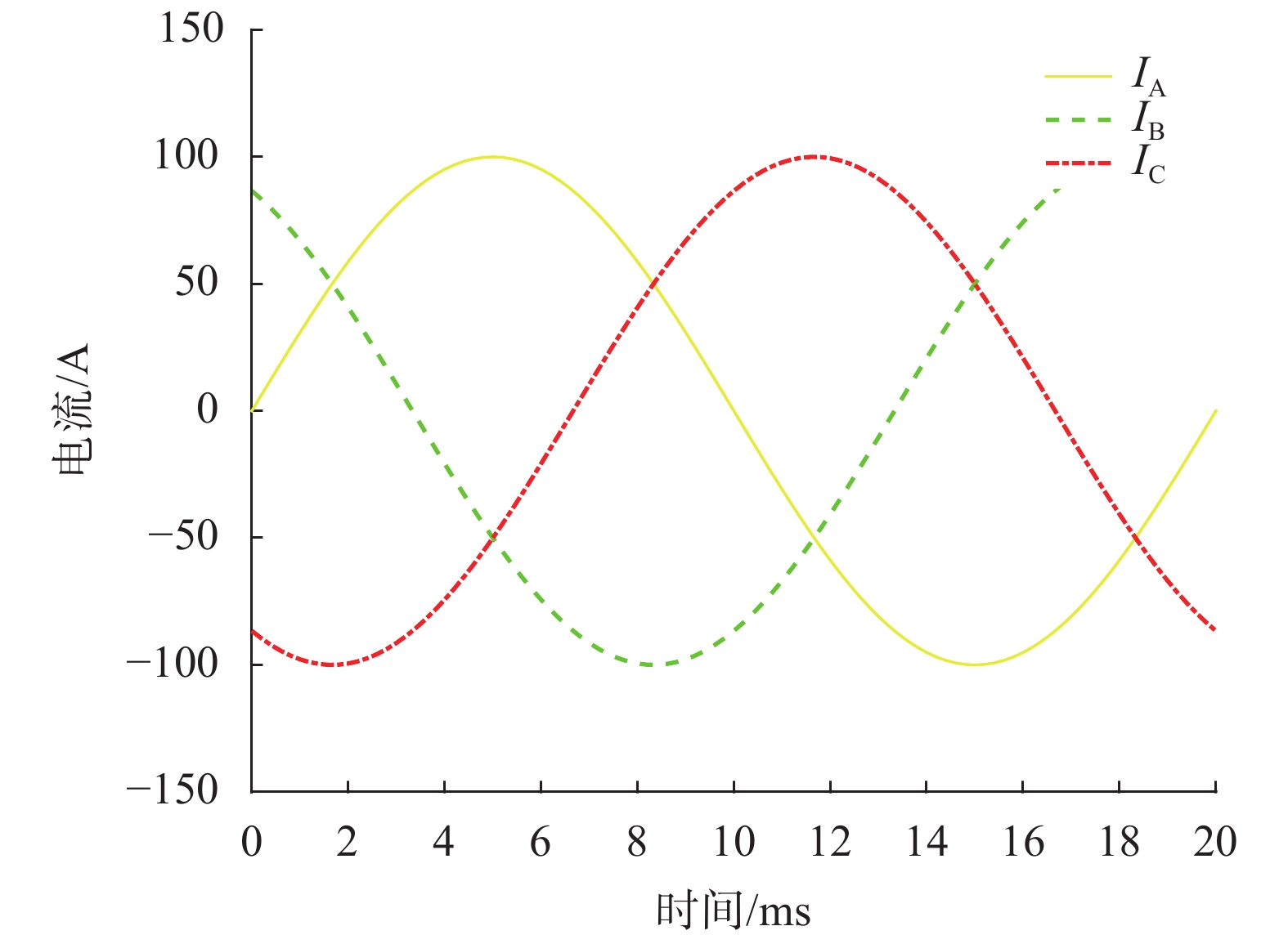
仿真试验中,采用Maxwell二维模型,三芯电力电缆的参数设置如下:R=45 mm,r=20 mm,A、B、C三相芯线的半径均为12.5 mm;x=3 mm,y=5 mm,即存在偏心;输入各芯线的正弦电流的幅值均为100 A,即IA=IB=IC=100 A,频率均为50 Hz,它们相互间的相位互差120°;仿真模型的边界设置为Balloon 边界,加载至以坐标原点为圆心、半径为450 mm的圆上;网格剖分方式为手动剖分,在源(即A、B、C三相芯线)的位置设置网格最大边长为1 mm;求解器类型为Transient求解器;仿真时长设置为电网电流一个周波的时间,即20 ms。此外,又设置了两个圆的几何模型,半径分别为45.1 mm和44.9 mm,在这两个圆和R=45 mm的圆所形成的两个夹层中,都设置网格最大边长为0.1 mm,即保证了在6个求解点(SA、SB、SC,
仿真试验输入的A、B、C三相芯线的正弦电流随时间变化的波形曲线如图4所示。
|
| 图 4 仿真试验中输入A、B、C三相芯线的正弦电流随时间变化的波形曲线 |
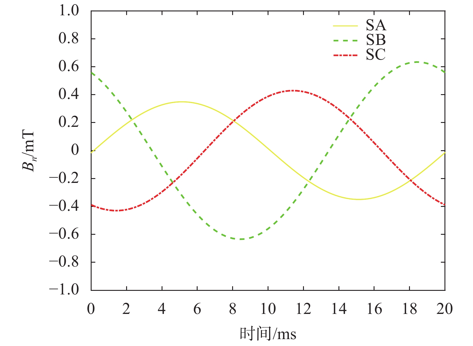
仿真试验获得的3个磁传感器SA、SB、SC处的磁感应强度沿n方向的分量随时间变化的波形曲线,如图5所示。将仿真试验的边界扩大一倍,网格最大长度缩小一半,两次仿真试验之间能量误差的变化小于1%,即认为原仿真模型的准确度已符合要求。
|
| 图 5 仿真试验所获得的SA、SB、SC处的磁感应强度沿n方向分量随时间变化的波形曲线(初始测量位置,0°) |
然后,以仿真试验所得到的相应磁感应强度作为已知条件,根据无偏心时的解析模型,即式(11)~式(13),求解三芯电力电缆各芯线的电流Ia、Ib、Ic。图6给出了计算得到的三芯电力电缆各芯线电流随时间变化的波形曲线。不难看出,计算结果与仿真试验所设置输入的各芯线电流波形存在较大的偏差,最大相对误差约26%。这表明,对偏心误差必须予以考虑。

|
| 图 6 未考虑偏心误差条件下复现出三芯电力电缆芯线电流波形与仿真试验所设置输入电流波形对比图 |
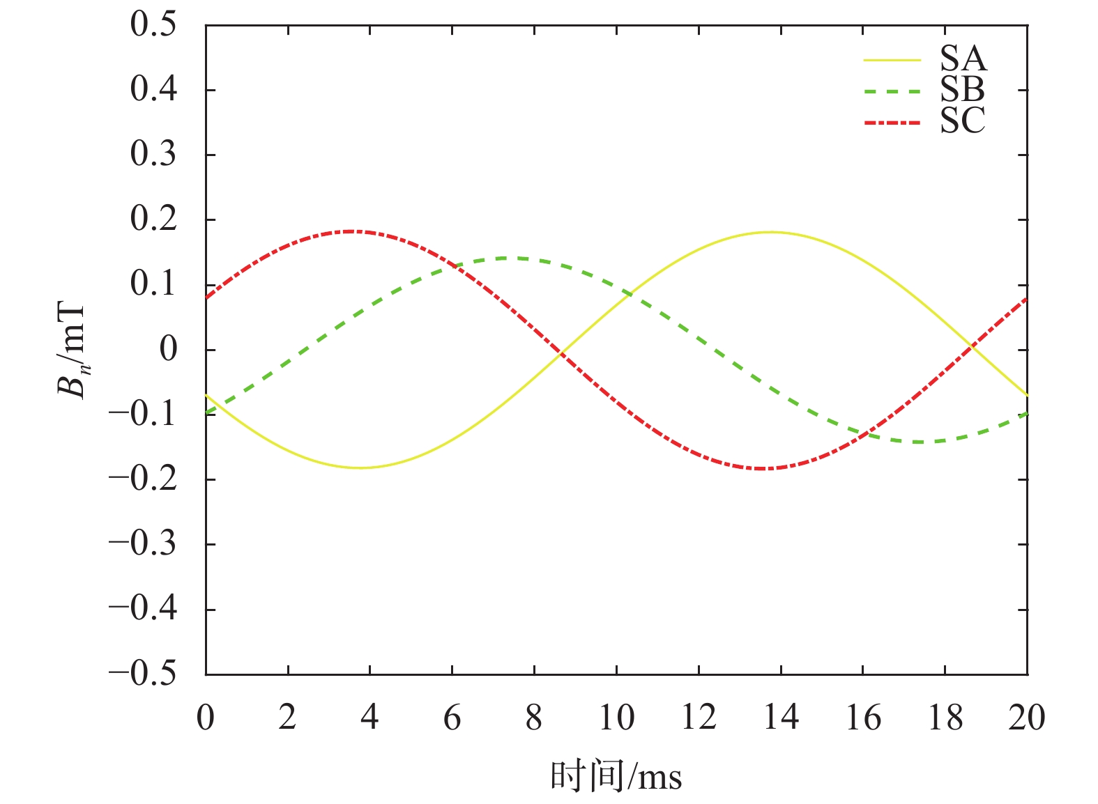
将磁传感器阵列相对于原安装位置沿安装平面周向旋转180°,并在新位置对沿电缆外表面轴向圆周的磁感应强度沿n方向的分量进行测量。
仍采用如图4所示的输入电流,再次进行仿真试验,得到的3个磁传感器SA、SB、SC在新位置处的磁感应强度沿n方向的分量随时间变化的波形曲线如图7所示。
|
| 图 7 仿真试验所获得的SA、SB和SC处的磁感应强度沿n方向分量随时间变化的波形曲线(旋转后测量位置,180°) |
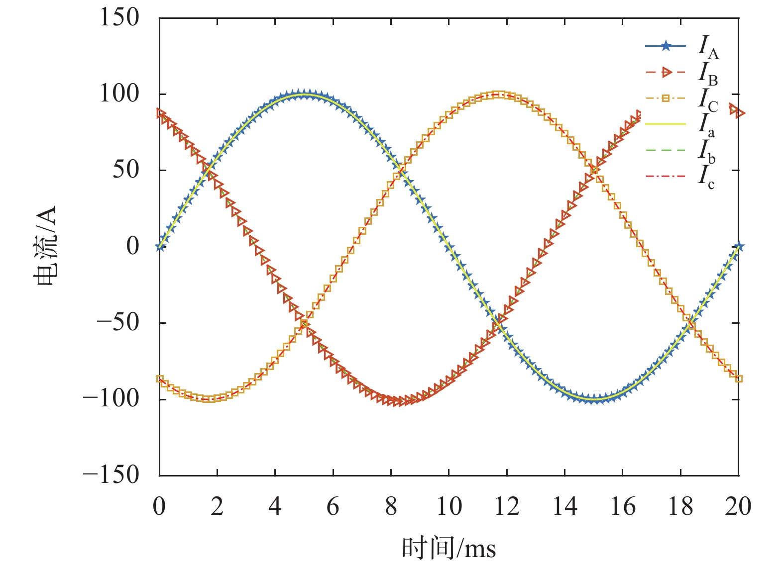
再采用式(23)、式(27)、式(31)~式(34)共同组成的超定方程组,对x、y、IA、IB、IC进行解析求解。注意,在已知6个独立方程求解5个未知量时,应采用最小二乘非线性拟合方法来获取最佳的未知量估计值。计算得到的各芯线正弦电流的幅值IA=100.18 A,IB=101.04 A,IC=99.83 A;电缆中心坐标参数x=2.86 mm,y=5.22 mm,以解析计算结果复现出的各芯线电流随时间变化的波形,如图8所示,其与仿真试验所设置输入的各芯线电流波形的误差曲线如图9所示。
|
| 图 8 利用解析模型计算复现的三芯电力电缆各芯线电流波形与仿真试验所设置输入电流波形对比图 |

|
| 图 9 利用解析模型计算复现的三芯电力电缆各芯线电流波形与仿真试验所设置输入电流波形的差值 |
从图9可以看出,在计及偏心误差后,三芯电力电缆各芯线电流的计算结果与仿真试验输入值非常接近,最大误差仅约为1%,从而很好地验证了本文所建立解析模型的正确性。
3 结束语本文将磁传感器阵列设计为可沿安装平面周向旋转,进而分别在初始的0°和旋转后的180°两个位置,测量由三相芯线共同产生的磁感应强度沿n方向的分量;由磁传感器阵列在上述两个位置的参数以及测得的磁感应强度,建立三芯电力电缆各芯线电流、磁传感器阵列中心实际位置以及所测量磁感应强度之间关系的解析模型,得到6个非线性方程。基于最小二乘法求解该非线性方程组,便可得到三芯电力电缆的偏心信息,以及计及偏心误差条件下三芯电力电缆各芯线电流的实际大小。
本文所提出的测量方法,可对以磁传感器测量三芯电力电缆各芯线电流的偏心误差进行计算和补偿。该方法克服了磁传感器阵列中心与三芯电力电缆中心存在偏心条件下,以磁传感器测量三芯电力电缆各芯线电流准确性不高的缺陷,可实现对三芯电力电缆各芯线电流的更准确测量。电磁场有限元仿真试验结果表明,本文提出的用磁传感器测量三芯电力电缆各芯线电流的偏心误差的计算和补偿方法准确性高、鲁棒性好,具有较高的实用价值。
| [1] |
韩立奎, 王海涛, 韩晓冰. 35 kV电缆设计中三芯与单芯电缆的选择与比较[J].
电线电缆, 2011(5): 15-16, 22.
DOI:10.3969/j.issn.1672-6901.2011.05.005 |
| [2] |
周远翔, 赵健康, 刘睿, 等. 高压/超高压电力电缆关键技术分析及展望[J].
高电压技术, 2014, 40(9): 2593-2612.
|
| [3] |
袁燕岭, 李世松, 董杰, 等. 电力电缆诊断检测技术综述[J].
电测与仪表, 2016, 53(11): 1-7.
DOI:10.3969/j.issn.1001-1390.2016.11.001 |
| [4] |
周承科, 李明贞, 王航, 等. 电力电缆资产的状态评估与运维决策综述[J].
高电压技术, 2016, 42(8): 2353-2362.
|
| [5] |
高云鹏, 谭甜源, 刘开培, 等. 电缆接头温度反演及故障诊断研究[J].
高电压技术, 2016, 42(2): 535-542.
|
| [6] |
刘刚, 张高言, 周凡. 基于等温松弛法的110 kV高压电缆老化状况评估[J].
高电压技术, 2014, 40(2): 497-504.
|
| [7] |
姜芸, 周韫捷. 分布式局部放电在线监测技术在上海500 kV交联聚乙烯电力电缆线路中的应用[J].
高电压技术, 2015, 41(4): 1249-1256.
|
| [8] |
OUYANG Y, HE J, HU J, et al. A current sensor based on the giant magnetoresistance effect: Design and potential smart grid applications[J].
Sensors, 2012, 12(11): 15520-15541.
DOI:10.3390/s121115520 |
| [9] |
何金良, 嵇士杰, 刘俊, 等. 基于巨磁电阻效应的电流传感器技术及在智能电网中的应用前景[J].
电网技术, 2011, 35(5): 8-14.
|
| [10] |
袁燕岭, 李世松, 董杰, 等. 用磁传感器测量三芯对称电缆相电流的方法[J].
中国测试, 2016, 42(8): 29-32.
|
| [11] |
李世松, 袁燕岭, 董杰, 等. 一种计算三芯电力电缆表面磁场的解析方法[J].
中国测试, 2017, 43(4): 95-99.
|
| [12] |
YUAN Y, DONG J, GAN J, et al. A three-core power cable online monitoring system based on phase current sensing[C]// Instrumentation and Measurement Technology Conference (I2MTC), 2017 IEEE International, 2017: 1-6.
|
 2019, Vol. 45


